Diagnostics
6-1. NA Engine (Diagnosis)
1. Overview
A: Reference
The on-board diagnostic (OBD) system detects and indicates malfunctions in the inputs and outputs of complex electronic controls. The engine warning light on the instrument panel alerts the driver of any malfunctions or breakdowns.
- In addition, a fail-safe function is installed to ensure a minimum level of driving performance in the event that the vehicle is unable to drive due to sensor failure.
-
The OBD system installed in vehicles with this type of engine complies with JOBD regulations. The OBD system monitors for failures of the components and systems described in the “Engine section” that affect emissions.
- When the system detects a malfunction, the engine warning light comes on. At the same time that the engine warning light comes on or flashes, the (DTC) table and engine freeze frame status are stored in the on-board computer.
- When the OBD system detects a malfunction, it stores engine status data (engine load, engine coolant temperature, fuel trim, engine RPM, vehicle speed, etc.) in the freeze frame in the on-board computer.
The stored freeze frame engine status data will be maintained until the (DTC) table is cleared, but the freeze frame
● If a fuel trim or misfire malfunction is detected while the engine status data in the frame is being maintained, it will be overwritten with the engine status data 4 in the freeze frame related to fuel trim or misfire.
If the malfunction does not occur again within three consecutive drive cycles, the engine warning light will go off but the (DTC) table will remain in the on-board computer.
- When diagnosing vehicle malfunctions, connect the Subaru Select Monitor to the vehicle.
B: Preparation Tools
| Illustration | Tool Number | Name | Use |
|---|---|---|---|
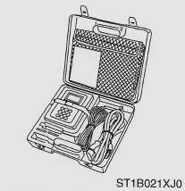 |
1B02XJ0 | Subaru Select Monitor III Kit | Used to diagnose electrical system faults. |
2. Engine Control Unit (ECU) I/O Signals
A. Specifications (Electrical Equipment)
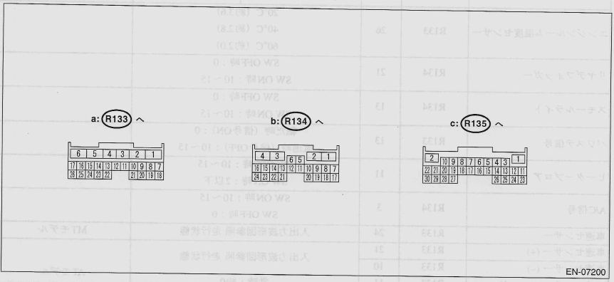
| Name | Connector Number | Terminal Number | Signal (V) | Reference | |
|---|---|---|---|---|---|
| Ignition switch ON (engine OFF) | Engine ON (idling) | ||||
| Main power supply 1 | R134 | 2 | 10 ~ 30 | 13 ~ 15 | |
| Main power supply 2 TA | R134 | 1 | 10 ~ 13 | 13 ~ 15 | |
| Backup power supply | R134 | 8 | 10 ~ 13 | 13 ~ 15 | |
| Sensor system power supply | R135 | 18 | 5 | 5 | |
| IG SW | R134 | 4 | 10 ~ 13 | 13 ~ 15 | |
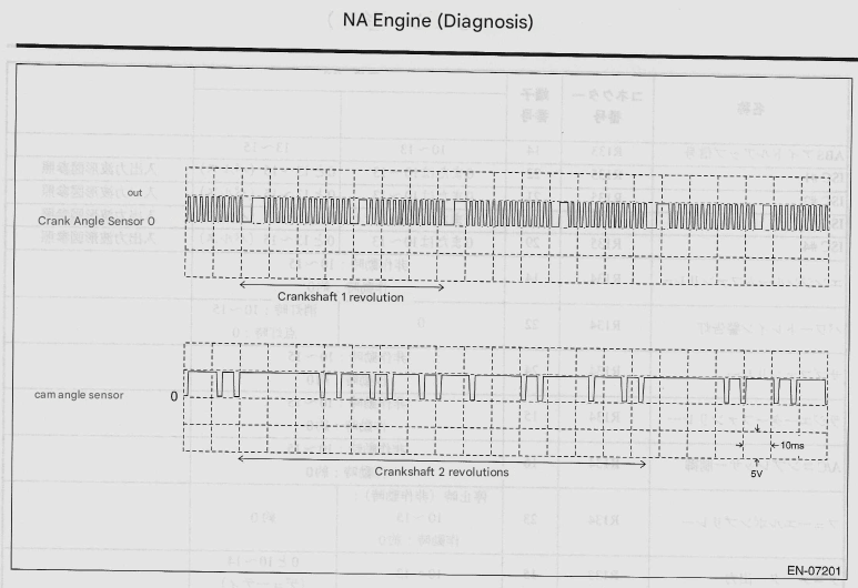
| Crank angle sensor | R135 | 16 | ~ 5 | See input/output waveform diagram | |
| Cam angle sensor | R135 | 6 | ~ 5 | See input/output waveform diagram | |
| Throttle opening | R135 | 3 | Fully close: 0.5 Fully open: 4.3 |
0.5 (Throttle fully closed) |
See also characteristic graph |
| Knock sensor | R135 | 23 | See input/output waveform diagram | ||
| Knock sensor shield | R135 | 24 | Always approx. 0 | ||
| Front O2 sensor | R135 | 14 | 0 ~ 1.0 | See input/output waveform diagram | |
| Front O2 sensor shield | R135 | 26 | Always approx. 0 | ||
| Rear O2 sensor | R133 | 16 | 0 ~ 1.0 | See input/output waveform diagram | |
| Rear O2 sensor shield | R133 | 17 | Always approx. 0 | ||
| Pressure sensor signal | R135 | 4 | ~ 4.3 | See also characteristic graph | |
| Water temperature sensor | R135 | 5 | About 40°C (about 2.0) About 60°C (about 1.2) About 80°C (about 0.8) |
See also characteristic graph | |
| A/C thermo signal | R134 | 6 | |||
| Intake air temperature sensor | R135 | 15 | About 20°C (about 3.0) About 40°C (about 2.0) About 60°C (about 1.3) |
See also characteristic graph | |
| Engine room remperature sensor | R133 | 26 | About 20°C (about 3.6) About 40°C (about 2.8) About 60°C (about 2.0) |
||
| Rear defogger | R134 | 21 | When SW is OFF: 0 SWON: 10~15 |
||
| Small light | R134 | 13 | When SW is OFF: 0 SWON: 10~15 |
||
| Power steering signal | R133 | 13 | When turning (signal ON): 0 Going straight (signal OFF): 10~15 |
||
| Heater proa | R134 | 11 | When SW is OFF: 10 to 15 SWON: 2 or less |
||
| A/C signal | R134 | 3 | SWON: 10~15 When SW is off: 0 |
||
| Vehicle speed sensor | R133 | 24 | Refer to input/output waveform diagram. | MT Model | |
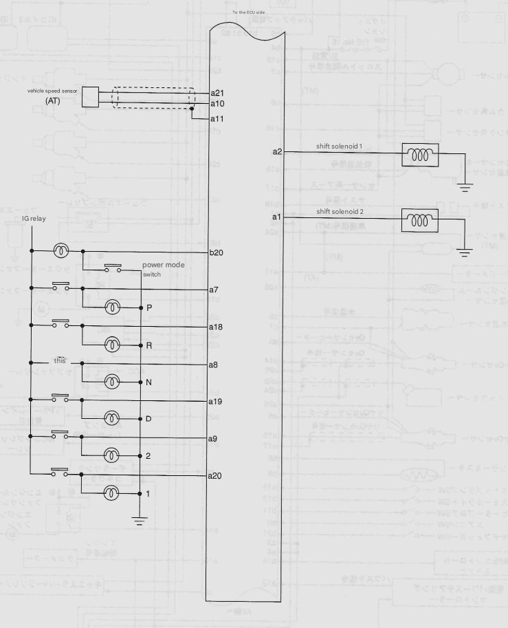
| Vehicle speed sensor (+) | R133 | 21 | Refer to input/output waveform diagram. | AT Model | |
| Vehicle speed sensor (-) | R133 | 10 | Refer to input/output waveform diagram. | AT Model | |
| Vehicle speed sensor shield | R133 | 11 | Always approx. 0 | AT Model | |
| Vehicle speed sensor | R133 | 12 | Refer to input/output waveform diagram. | AT Model | |
| Plake SW | R134 | 18 | Brake pedal depressed: 10~15 Brake pedal released: 0 |
||
| Power mode SW | R134 | 20 | During SWON: 0 When SW is OFF: 10~15 |
AT model | |
| P range | R133 | 7 | P range: 10~15 Other than P range: 0 |
AT model | |
| R range | R133 | 18 | R range: 10~15 Other than R range: 0 |
AT model | |
| N range | R133 | 8 | N range: 10~15 Other than N range: 0 |
AT model | |
| D range | R133 | 19 | D range: 10~15 Other than D range: 0 |
AT model | |
| 2 ranges | R133 | 9 | 2 range: 10~15 Other than 2 ranges: 0 |
AT model | |
| 1 range | R133 | 20 | 1 range: 10~15 Other than 1 range: 0 |
AT model | |
| Test terminal | R134 | 19 | Terminal release: 10~15 When terminal is connected: 0 |
||
| Ignition output #1 | R135 | 10 | About 0 | See input/output waveform diagram | |
| Ignition output #2 | R135 | 9 | About 0 | See input/output waveform diagram | |
| Injector #1 | R135 | 20 | 10~13 | See input/output waveform diagram | |
| Injector #2 | R135 | 19 | 10~13 | See input/output waveform diagram | |
| Injector #3 | R135 | 28 | 10~13 | See input/output waveform diagram | |
| Injector #4 | R135 | 27 | 10~13 | See input/output waveform diagram | |
| Alternator | R133 | 23 | When stopped (not in operation): 5.0~8.5 When activated: 0 and 5.0~8.5 (duty) |
Period 50ms | |
| Select monitor | R134 | 9 | About 10~15 | ||
| ABS idle up signal | R133 | 14 | 10~13 | 13~15 | |
| ISC #1 | R135 | 22 | 0 or 10 to 13 | 0 and 13~15 (pulse) | See input/output waveform diagram |
| ISC #2 | R135 | 21 | 0 or 10 to 13 | 0 and 13~15 (pulse) | See input/output waveform diagram |
| ISC #3 | R135 | 30 | 0 or 10 to 13 | 0 and 13~15 (pulse) | See input/output waveform diagram |
| ISC #4 | R135 | 29 | 0 or 10 to 13 | 0 and 13~15 (pulse) | See input/output waveform diagram |
| Engine room fan relay | R134 | 14 | Non-operating: 10~15 When in operation approx. 0 |
||
| Powertrain warning light | R134 | 22 | 0 | When lights are off: 10~15 Wheb lit: 0 |
|
| Sub fan relay | R134 | 24 | Non-operating: 10~15 When in operation approx. 0 |
||
| Radiator fan relay | R134 | 15 | Non-operating: 10~15 When in operation approx. 0 |
||
| A/C compressor Control | R134 | 16 | Non-operating: 10~15 When in operation approx. 0 |
||
| Fuel pump relay | R134 | 23 | When stopped (not operating): 10~15 When in operation approx. 0 |
About 0 | |
| Tachometer output | R133 | 15 | 10~13 | 0 and 10-14 (duty) | |
| Self shut off | R134 | 10 | Below 1V | ||
| CPC solenoid | R135 | 8 | 10~13 | See input/output waveform diagram | |
| Front O2 sensor heater | R133 | 5 | 10~13 | See input/output waveform diagram | |
| Rear O2 sensor heater | R133 | 6 | 10~13 | See input/output waveform diagram | |
| Shift solenoid 1 | R133 | 2 | 1st gear: 10~15 2nd gear: 10~15 3rd gear: 0 |
AT model | |
| Shift solenoid 2 | R133 | 1 | 1st gear: 10~15 2nd gear: 10~15 3rd gear: 0 |
AT model | |
| Sensor ground 1 | R135 | 7 | Always approx. 0 | ||
| Sensor ground 2 | R135 | 17 | Always approx. 0 | ||
| Sensor ground (rear O2 sensor) | R133 | 25 | Always approx. 0 | ||
| Sensor ground (body) | R134 | 5 | Always approx. 0 | ||
| Power ground | R133 | 3 | Always approx. 0 | ||
| Power ground | R133 | 4 | Always approx. 0 | ||
| Control system ground | R135 | 1 | Always approx. 0 | ||
| Control system ground | R135 | 2 | Always approx. 0 | ||
- Engine
3. Inspection mode
A: Carry out the diagnosis shown in the following diagnostic code (DTC) table.
When performing a diagnosis that is not shown in the diagnostic code (DTC) table, refer to the drive cycle section. (See 6-12 “Drive Cycle”.)
| DTC | Category | Category |
|---|---|---|
| P0031 | O2 Sensor Heater Circuit (LOW) (Bank 1 Sensor 1) | |
| P0032 | O2 Sensor Heater Circuit (HIGH) (Bank 1 Sensor 1) | |
| P0037 | O2 Sensor Heater Circuit (LOW) (Bank 1 Sensor 2) | |
| P0038 | O2 Sensor Heater Circuit (HIGH) (Bank 1 Sensor 2) | |
| P0107 | Intake pressure sensor circuit (LOW) | |
| P0108 | Intake pressure sensor circuit (HIGH) | |
| P0112 | Intake air temperature sensor circuit (LOW) | |
| P0113 | Intake air temperature sensor circuit (HIGH) | |
| P0117 | Water temperature sensor circuit (LOW) | |
| P0118 | Water temperature sensor circuit (HIGH) | |
| P0122 | Throttle position sensor A circuit (LOW) | |
| P0122 | Throttle position sensor A circuit (HIGH) | |
| P0130 | O2 sensor circuit (Bank 1 Sensor 1) | |
| P0136 | O2 sensor circuit (Bank 1 Sensor 2) | |
| P0327 | Knock sensor 1 circuit (LOW) | |
| P0328 | Knock sensor 1 circuit (HIGH) | |
| P0335 | Crank angle sensor A system circuit | |
| P0340 | Cam angle sensor A system circuit 1 | |
| P0350 | Ignition coil system circuit | |
| P0444 | Canister purge solenoid circuit (LOW) | |
| P0445 | Canister purge solenoid circuit (HIGH) | |
| P0500 | Vehicle speed sensor system | |
| P0562 | Charging circuit (LOW) | |
| P0562 | Charging circuit (HIGH) | |
| P0705 | AT Range SW circuit | |
| P0720 | AT vehicle speed sensor circuit | |
| P0753 | AT shift solenoid 1 circuit (shift solenoid A) | |
| P0758 | AT shift solenoid 2 circuit (shift solenoid B) | |
| P0790 | Mode SW circuit | |
| P1510 | ISC signal line 1 circuit (LOW) | |
| P1511 | ISC signal line 1 circuit (HIGH) | |
| P1512 | ISC signal line 2 circuit (LOW) | |
| P1513 | ISC signal line 2 circuit (HIGH) | |
| P1514 | ISC signal line 3 circuit (LOW) | |
| P1515 | ISC signal line 3 circuit (HIGH) | |
| P1516 | ISC signal line 4 circuit (LOW) | |
| P1517 | ISC signal line 4 circuit (HIGH) | |
| P1521 | Brake signal circuit | |
| P1522 | Electrical load signal system circuit | |
| P1525 | Blower fan circuit | |
| P1559 | Intake system | |
| P1560 | Backup power supply |
- Preparation for Inspection
- Make sure there is about half a fuel tank [10~20 liters (2.7~5.3 US gal, 2.2~ 4.4 Imp gal)] remaining and the battery voltage is 12 V or higher.
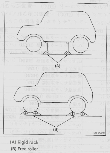
- Use a garage jack to jack up the vehicle and place it on a rigid rack or run the vehicle on free rollers.
Warning:
- Before jacking up the vehicle, make sure the parking brake is on.
- Do not use a pantograph jack instead of a rigid rack.
- Attach a rope or wire to the front or rear towing hook to prevent the front wheel from swaying sideways.
- Before you spin the wheels, make sure there is no one in front of the vehicle, and keep no one in front of the vehicle while you are spinning the wheels.
- Make sure there are no obstacles near the wheels, especially all four wheels if you have an AWD model.
- While working, do not suddenly press or release the clutch pedal or accelerator pedal, regardless of the engine speed. Sudden operation may cause the vehicle to separate from the free rollers.
- To prevent the vehicle from slipping due to vibration, do not place anything between the rigid rack and the vehicle.
- Subaru Select Monitor
- After clearing the memory, check that no unsolved fault data remains. (See 6-13 “Clear Memory Mode”.)
- Warm up the engine.
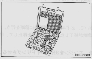
- Prepare the Subaru Select Monitor Kit. 6-2 “Overview and Preparation Tools.”
- Prepare a computer with the Spartan Select Monitor installed.
-
Connect the USB cable to the SDI (Subaru Diagnostic Interface) and the computer’s USB port (Subaru Select Monitor dedicated port).
Reference:
- The Subaru Select Monitor dedicated port refers to the USB port used when installing the Subaru Select Monitor.
- Connect the diagnostic cable to SDI.
-
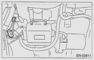
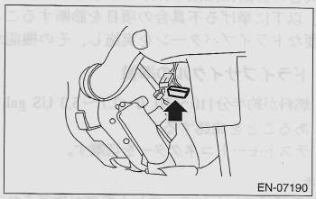
Connect the test mode connector (A) located at the bottom of the instrument panel (driver’s side).
-
Connect the SDI to the data link connector installed at the bottom of the instrument panel (driver’s seat side).
Notice: Do not connect any scan tools other than the Subaru Select Monitor.
- Start your computer.
- Turn the ignition switch ON (engine OFF) and launch the “Subaru Select Monitor PC Application.”
- On the main menu screen, select “Individual System Check.”
- On the «System Selection Menu» screen, select {Engine}.
- After the engine type information is displayed, click the [OK] button.
- On the “Engine Fault Diagnosis” screen, select “D Check.”
- When the message “Do you want to perform a D check?” appears on the screen, click the [Next] button.
-
Follow the next steps as instructed on the screen.
Reference:
- If a malfunction remains in the memory, the corresponding DTC will be displayed on the screen.
- For detailed operating procedures, refer to the “Subaru Select Monitor PC Application Help.”
- For details on the DTC, refer to the diagnostic code (DTC) table. (See Diagnostics Code (DTC) table on page 6-14.)
- If the speed difference between the front and rear wheels occurs, the ABS warning light may come on, but this is not a malfunction. After the engine control diagnosis is complete, perform the ABS memory clear procedure in the self-diagnosis function.
4. Drive cycle
A: Procedure
The drive patterns shown below are used to diagnose malfunctions. By implementing the specified drive patterns, the malfunctions listed below can be diagnosed. After repairing the malfunctions listed below, be sure to implement the required drive pattern and check that the function has been restored correctly.
- Preparing the Drive Cycle
- Make sure there is about half a tank of fuel [10~20 liters (2.7~5.3 US gal, 2.2~4.4 Imp gal)] remaining and the battery voltage is 12V or higher.
- Disconnect the test mode connector.
Reference:
- Unless the engine coolant temperature is specified at start-up, always perform the diagnosis after the engine has warmed up.
- If the DTC has an * mark, perform the diagnosis twice. After the first diagnosis is completed, stop the engine and perform the second diagnosis under the same conditions.
- Drive cycle 1 (Drive for 20 minutes at 55-65 km/h, then idle the engine for 3 minutes.)
Reference:
- If it is not possible to drive continuously for 20 minutes, drive the vehicle while meeting the following conditions 4 to 5 times without turning off the engine.
- Each run lasts approximately 5 minutes.
- Drive at a constant speed (55-65km/h).
- Reduce acceleration and deceleration (throttle operation) while driving at a constant speed.
| DTC | Project | Condition |
|---|---|---|
| *P0133 | O2 Sensor response (Bank 1 Sensor 1) | |
| *P0139 | O2 Sensor response (Bank 1 Sensor 2) | |
| *P0171 | Fuel System 1 (Lean) | |
| *P0172 | Fuel System 1 (Rich) | |
| *P0301 | #1 Cylinder misfire | |
| *P0302 | #2 Cylinder misfire | |
| *P0303 | #3 Cylinder misfire | |
| *P0304 | #4 Cylinder misfire | |
| *P0420 | Catalyst system |
5. Clear Memory Mode
A: Operation
- On the main menu screen, select “Individual System Check.”
- On the «System Selection Menu» screen, select {Engine}.
- After the engine type information is displayed, click the [OK] button.
- On the ENGINE DIAGNOSIS screen, select MEMORY CLEAR.
- When the message “Do you want to clear memory?” appears on the screen, click the [Yes] button.
- When “Executed” and “Turn IG SW OFF” are displayed on the screen, turn the ignition switch OFF.
Reference:
- For detailed operating procedures, refer to the “Subaru Select Monitor PC Application Help.”
6. Diagnostic Code (DTC) List
A: List
| DTC | Project | Reference |
|---|---|---|
| P0037 | O2 Sensor Heater Circuit (LOW) (Tire 1 Sensor 2) | (See 6-15 "Diagnostic Procedures Using Diagnostic Codes (DTCs)", DTC P0037 (See "O2 Sensor Heater Circuit (LOW) (Bank 1 Sensor 2)" |
| P0038 | O2 Sensor Heater Circuit (HIGH) (Bank 1 Sensor 2) | (See 6-17 "Diagnostic Procedures Using Diagnostic Codes (DTCs)", DTC P0038 (See "O2 Sensor Heater Circuit (HIGH) (Bank 1 Sensor 2)" |
| P0136 | O2 Sensor Circuit (Bank 1 Sensor 2) | 6-19 "Diagnostic Procedures Using Diagnostic Codes (DTCs) DTC P0136 (See "O2 Sensor Circuit (Bank 1 Sensor 2)" |
| P0139 | O2 Sensor Response (Bank 1 Sensor 2) | (See 6-22 "Diagnostic Procedures Using Diagnostic Codes (DTCs)," DTC P0139 (See "O2 Sensor Response (Bank 1 Sensor 2)" |
| P0420 | Catalyst system | (See 6-24 "Diagnostic Procedures Using Diagnostic Codes (DTCs)," DTC P0420 (See "Catalyst Systems.") |
7. Diagnostic Procedures When Using Diagnostic Codes (DTC)
A: DTC P0037 O2 Sensor Heater Circuit (LOW) (Bank 1 Sensor 2)
Notice: After repairing or replacing the defective parts, execute the clear memory mode (see “Clear Memory Mode, Operation” on page 6-13) and the inspection mode (see “Inspection Mode, Procedure” on page 6-9).
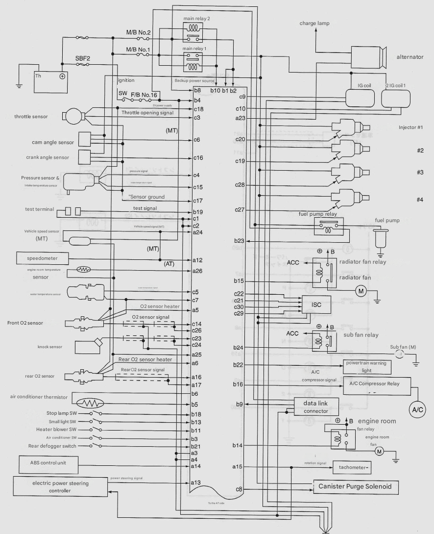
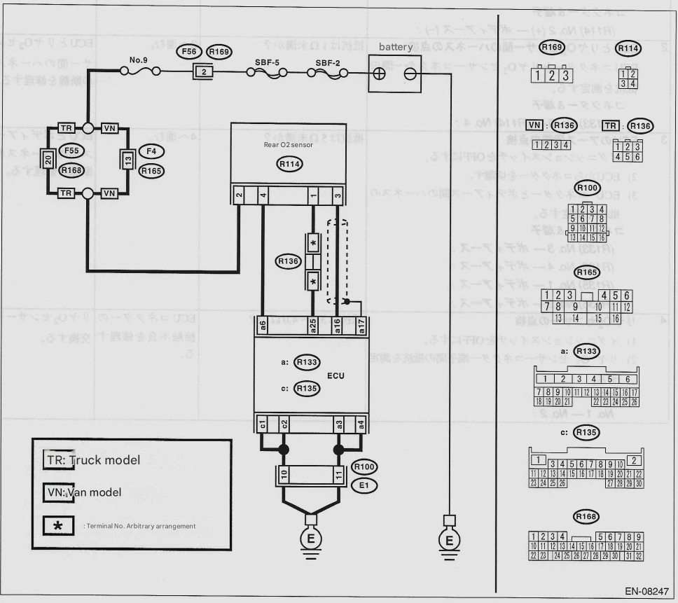
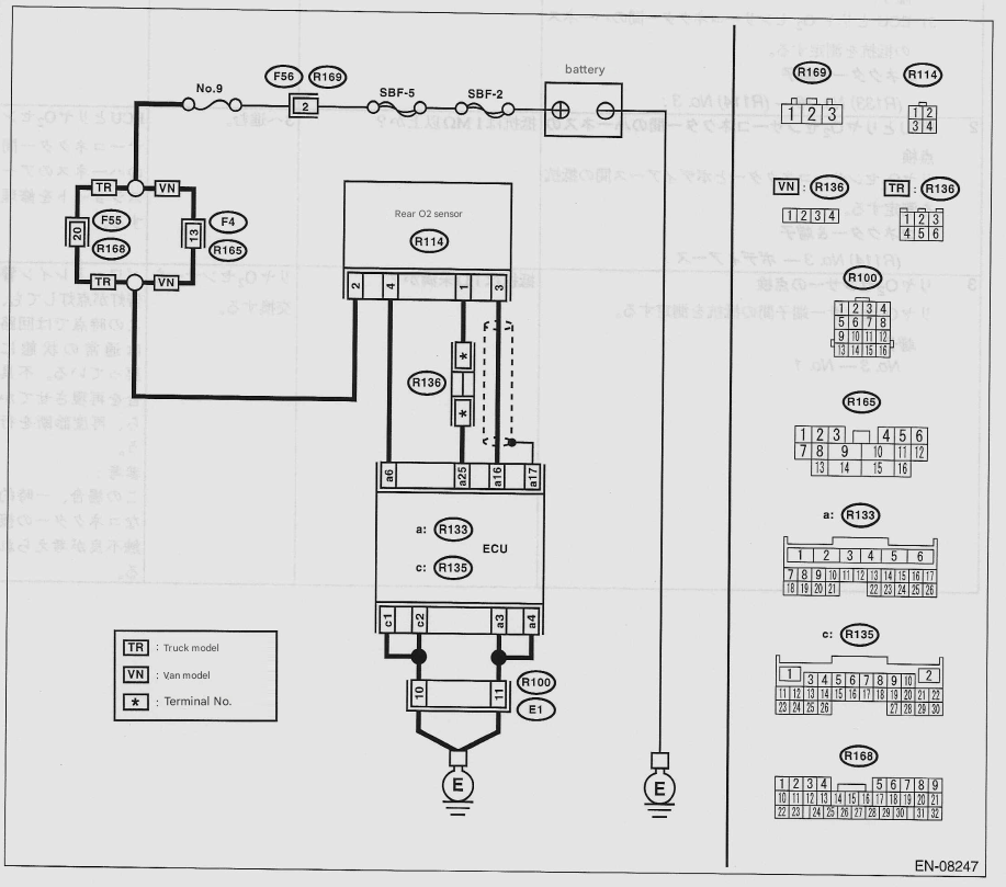
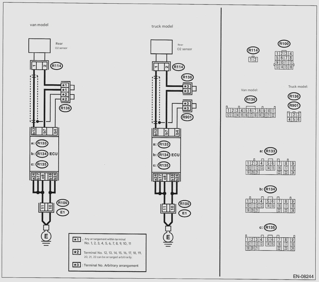
Wiring diagram:
| Step | Check | Yes | No |
|---|---|---|---|
|
Step 1. Check the power supply to the rear 2 sensors 1. Turn the ignition switch OFF. 2. Disconnect the connector from the rear O2 sensor. 3. Turn the ignition switch ON. 4. Between the rear O2 sensor connector and body ground measure voltage. Connectors & terminals: (R114) No.2 (+) - Body Earth (-) |
Is the voltage 10V or more? | Proceed to step 2. | Repair the power supply line. |
| Step 2. Check the harness between the ECU and the rear O2 sensor Measure the resistance between the ECU connector and the Rear O2 sensor connector. Connectors & terminals: (R133) No. 6 - (R114) No. 4 |
Is the resistance less than 1MΩ? | Proceed to step 3. | Repair the break in the harness between the ECU and the rear O2 sensor. |
| Step 3. Check the ECU earth circuit 1. Turn the ignition switch OFF. 2. Disconnect the connector from the ECU. 3. Check the harness between the ECU connector and the body ground. Measure resistance. Connectors & terminals: (R133) No. 3 - Body Earth (R133) No. 4 - Body Earth (R135) No. 1 - Body Earth (R135) No. 2 - Body Earth |
Is the resistance below 52? | Proceed to step 4. | Repair the break in the hardness between the ECU and the body ground. |
| Step 4. Check the rear 2 sensors 1. Turn the ignition switch OFF. 2. Measure the resistance between the rear O2 sensor connector terminals. Terminals: No. 1 - No.2 |
Is the resistance 3.0~4.02? | Repair the poor contact of the ECU connector. | Rear O2 sensor exchange. |
B: DTC P0038 O2 Sensor Heater Circuit (HIGH) (Bank 1 Sensor 2)
Notice: After repairing or replacing the defective parts, execute the clear memory mode (see “Clear Memory Mode, Operation” on page 6-13) and the inspection mode (see “Inspection Mode, Procedure” on page 6-9).
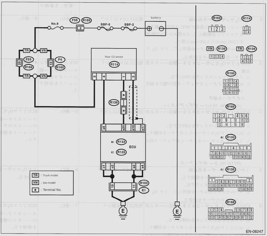
Wiring diagram:

| Step | Check | Yes | No |
|---|---|---|---|
| Step 1. Check the harness between the ECU and the rear O2 sensor 1. Turn the ignition switch OFF. 2. Disconnect the connector from the rear O2 sensor. 3. Measure the voltage between the ECU and body ground. Connectors & Terminals: (R133) No. 6 (+) - Body Earth (-) |
Is the voltage 10V or higher? | Repair the power short in the harness between the ECU and the rear O2 sensor connector. | Proceed to step 2. |
| Step 2. Check the ECU earth circuit 1. Disconnect the connector from the ECU. 2. Measure the resistance of the harness between the ECU connector and body ground. Connectors & Terminals: (R133) No. 3 - Body Earth (R133) No. 4 - Body Earth (R135) No. 1 - Body Earth (R135) No. 2 - Body Earth |
Is the resistance below 52? | Repair the poor contact of the ECU connector. If there is a problem, replace the ECU. | Repair the break in the harness between the ECU connector and the body ground. |
C: DTC P0136 O2 Sensor Circuit (Bank 1 Sensor 2)
Notice: After repairing or replacing the defective parts, execute the clear memory mode (see “Clear Memory Mode, Operation” on page 6-13) and the inspection mode (see “Inspection Mode, Procedure” on page 6-9).
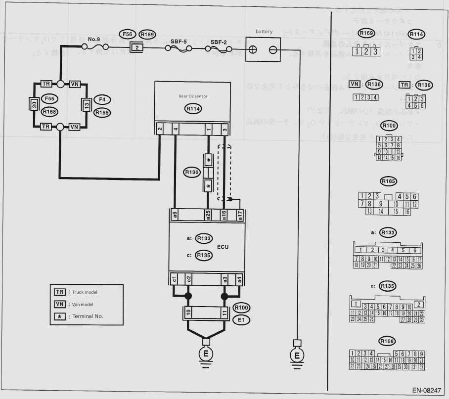
Wiring diagram:
| Step | Check | Yes | No |
|---|---|---|---|
| Step 1. Check the screen for other DTCs. | Are any other DTCs showing up? | Check the DTCs using the "Diagnostic Code (DTC) Table". (See "Diagnostic Code (DTC) Table" on page 6-14.) | Go to Step 2. |
| Step 2. Checking rear 2 sensor data 1. Warm up the engine until the engine coolant temperature exceeds 70°C (158°F), then maintain the engine speed between 2,000 rpm and 3,000 rpm for two minutes. 2. Use the Subaru Select Monitor to read the rear O2 sensor signal data. |
Is the voltage below 1.0V? | Proceed to Step 3. | Proceed to Step 8. |
| Step 3. Check the harness between the ECU and the rear O2 sensor connector. 1. Turn the ignition switch ON. 2. Measure the voltage between the ECU connector and body ground. Connectors & Terminals: (R133) No. 16 (+) - Body Earth (-) |
Is the voltage 10V or higher? | Repair the power short in the harness between the ECU and the rear O2 sensor connector. | Proceed to Step 4. |
| Step 4. Harness between ECU and rear O2 sensor connector: Inspection 1. Turn the ignition switch OFF. 2. Disconnect the connector from the ECU and the rear O2 sensor. 3. Measure the resistance between the rear O2 sensor connector and body ground. Connectors & Terminals: (R114) No. 3 - Body Earth |
Is the resistance greater than 1MΩ? | Proceed to Step 5. | Repair the ground short in the harness between the ECU and the rear O2 sensor connector. |
| Step 5. Check the rear 2 sensor data 1. Connect all connectors. 2. Idle the engine. 3. Idle the engineUse the Subaru Select Monitor to check the rear O2 sensor. Read the data of the sensor signal. |
Is the voltage 0.7 to 0.09V? | Proceed to Step 6. | Replace the rear O2 sensor. |
| Step 6. Harness between ECU and rear O2 sensor connector: Inspection: 1. Turn the ignition switch OFF. 2. Disconnect the connectors from the ECU and the rear O2 sensor. 3. Measure the resistance of the harness between the ECU and the rear O2 sensor connector. Connectors & Terminals: (R133) No. 16 - (R114) No.3 |
Resistance less than 1MΩ? | Proceed to Step 7. | Repair the open circuit in the harness between the ECU and the rear O2 sensor connector. |
| Step 7. Harness between rear O2 sensor and ECU connector Inspection: 1. Connect the connector to the ECU and rear O2 sensor.. 2. Turn the ignition switch ON. 3. Replace the rear O2 sensor harness connector and tighten the ground terminal. Connectors & Terminals: (R114) No. 3 (+) - Body Earth (-) |
Is the voltage less than 0.2V? | Repair poor contact in the rear O2 sensor connector and ECU connector. | Replace the rear O2 sensor. |
| Step 8. Engine System Inspection Inspect the exhaust system components. Reference: Check the following items: - Loose and incompletely installed exhaust system parts - Damage to parts (cracks, holes, etc.) - Parts between the front O2 sensor and the reas O2 sensor - Loose and incomplete installation |
Is there a problem with the exhaust system? | Repair or replace defective parts. | Replace the rear O2 sensor. |
D: DTC P0139 O2 Sensor Response (Bank 1 Sensor 2)
Notice: After repairing or replacing the defective parts, execute the clear memory mode (see “Clear Memory Mode, Operation” on page 6-13) and the inspection mode (see “Inspection Mode, Procedure” on page 6-9).
Wiring diagram:
| Step | Check | Yes | No |
|---|---|---|---|
| Step 1. Inspection: 1. Turn the ignition switch OFF. 2. Disconnect the connectors from the ECU and rear O2 sensor.. 3. Measure the resistance of the harness between the ECU and the rear O2 sensor connector. Connectors & Terminals: (R133) No. 16 - (R114) No. 3 |
Resistance less than 1MΩ? | Proceed to Step 2. | Repair the break in the harness between the power connectors. |
| Step 2. Harness between ECU and rear O2 sensor connector Inspection: Measure the resistance between the rear O2 sensor connector and body ground. Connectors & Terminals: (R114) No. 3 - Body Earth |
Is the resistance greater than 1MΩ? | Proceed to Step 3. | Repair the short to earth in the harness between the power connectors. |
| Step 3. Check the rear 2 sensors Measure the resistance between the rear O2 sensor terminals.. Terminals: No. 3 - No. 1 |
Is the resistance less than 1MΩ? | Rear O2 sensor exchange | Even if the powertrain warning light comes on, the circuit has returned to normal at this point. Recreate the fault and perform the diagnosis again. Reference: In this case, a temporary connector contact failure may be the cause. |
E: DTC P0420 Catalyst system
Notice: After repairing or replacing the defective parts, execute the clear memory mode (see “Clear Memory Mode, Operation” on page 6-13) and the inspection mode (see “Inspection Mode, Procedure” on page 6-9).
Wiring diagram:
| Step | Check | Yes | No |
|---|---|---|---|
| Step 1. Inspecting the exhaust system Check for gas leaks or air inhalation caused by loose or missing nuts and bolts, and for holes in the exhaust pipe. Reference: Check the following locations. - Between the cylinder head and the front exhaust pipe - Between the front exhaust pipe and the front catalyst - Between the front and rear catalysts - The front O2 sensor or rear O2 sensor is loose or incompletely installed. |
Is there a problem with the exhaust system? | Repair or replace the exhaust system | Proceed to Step 2. |
| Step 2. Checking the waveform data on the Subaru Select Monitor (while driving) 1. Drive at a constant speed of 55-66km/h. 2. After 5 minutes have elapsed in the state of Step 1), use the Subaru Select Monitor to read the waveform data while the vehicle is still driving. - Normal: 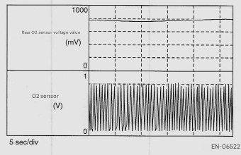 - When abnormal (many inversions) 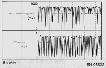 |
Is the normal waveform displayed? | Even if the powertrain warning light comes on, the circuit has returned to normal at this point. Recreate the fault and perform the diagnosis again. Reference: In this case, a temporary connector contact failure is suspected. |
Proceed to Step 3. |
| Step 3. Checking the waveform data on the Subaru Select Monitor (while idling) 1. Idle the vehicle. 2. While in Step 1), use the Subaru Select Monitor to read the waveform data. - Normal: 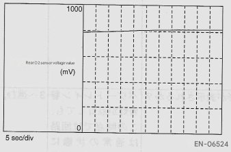 - Abnormality 1 (many inversions) 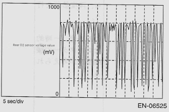 - Abnormality 2 (noise mixed) 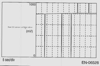 |
Is the normal waveform displayed? | Proceed to Step 4. | - If the waveform of abnormality 1 is displayed: Go to Step 4. - If the waveform of abnormality 2 is displayed, proceed to Step 5. |
| Step 4. Inspecting the catalyst | Is there damage to the catalyst? | Replace the catalyst | Proceed to Step 5. |
| Step 5. Check the rear 2 sensor connector and intermediate connector | Has water gotten into the connector? | Completely prevent water ingress. | Proceed to Step 6. |
| Step 6. Harness between ECU and rear O2 sensor connector Inspection: 1. Turn the ignition switch OFF. 2. Disconnect the connectors from the ECU and rear O2 sensor. 3. Measure the resistance of the harness between the ECU and the rear O2 sensor connector. Connectors & Terminals: (R133) No. 16 - (R114) No. 3 (R133) No. 25 - (R114) No. 1 |
Resistance less than 1MΩ? | Proceed to Step 7. | Repair the harness and connectors. Reference: Repair the following locations: - Disconnection in the harness between the ECU and the rear O2 sensor connector. - Poor contact at the short connector. |
| Step 7. Harness between ECU and rear O2 sensor connector Inspection: 1. Connect the connector to the ECU. 2. Turn the ignition switch ON. 3. Measure the voltage between the rear O2 sensor connector and body ground. Connectors & Terminals: (R114) No. 3 (+) - Body Earth (-) |
Is the voltage 0.2 to 0.5V? | Proceed to Step 8. | Repair the harness and connector. Reference: Repair the following locations: - Open circuit between ECU and rear O2 sensor - Poor contact of the ECU connector |
| Step 8. Check the rear 2 sensor shield 1. Turn the ignition switch OFF. 2. Expose the sensor shield on the body side harness of the rear O2 sensor connector. 3. Measure the resistance between the sensor shield and body ground. |
Is the resistance less than 1MΩ? | Replace the rear O2 sensor. | Repair the disconnection in the rear O2 sensor heater circuit. |
6-2. SC Engine (Diagnosis)
1. Clear memory mode
A: Operation
- On the main menu screen, select “Individual System Check.”
- On the «System Selection Menu» screen, select {Engine}.
- After the engine type information is displayed, click the [OK] button.
- On the
screen, select {Memory Clear}. - When the message “Do you want to clear memory?” appears on the screen, click the [Yes] button.
- When “Executed” and “Turn IG SW OFF” are displayed on the screen, turn the ignition switch OFF.
Reference:
- For detailed operating procedures, refer to the “Subaru Select Monitor PC Application Help.”
2. Diagnostic Code (DTC) List
A: List
| DTC | Project | Reference |
|---|---|---|
| P0136 | O2 Sensor Circuit (Bank 1 Sensor 2) | (See "Diagnostic Procedure When Using Diagnostic Code (DTC) DTC P0136 02 Sensor System Circuit (Bank 1 Sensor 2)" on page 6-30.) |
| P0136 | O2 Sensor Circuit (Bank 1 Sensor 2) | (See "Diagnostic Procedure When Using Diagnostic Code (DTC) DTC P0136 02 Sensor System Circuit (Bank 1 Sensor 2)" on page 6-30.) |
3. Diagnostic procedure when using diagnostic codes (DTC)
A: DTC P0136 O2 Sensor Circuit (Bank 1 Sensor 2)
Notice: After repairing or replacing the defective parts, execute the clear memory mode (see “Clear Memory Mode, Operation” on page 6-28).
Wiring diagram:
| Step | Check | Yes | No |
|---|---|---|---|
| Step 1. Check the screen for any other DTCs | Are there any other DTCs showing up? | Check the DTCs using the "Diagnostic Code (DTC) Table." (See "Diagnostic Code (DTC) Table" on page 6-29.) | Proceed to Step 2. |
| Step 2. Checking the rear 2 sensor data | Is the voltage below 1.0V? | Proceed to Step 3. | Proceed to Step 8. |
| Step 3. Harness between ECU and rear O2 sensor connector Inspection 1. Turn the ignition switch ON. 2. Measure the voltage between the ECU connector and body ground. Connectors & terminals (R134) No. 12 (+) - Body Earth (-) |
Is the voltage 10V or higher? | Repair the power short in the harness between the ECU and the rear O2 sensor connector. | Proceed to Step 4. |
| Step 4. Harness between ECU and rear O2 sensor connector Inspection 1. Turn the ignition switch OFF. 2. Disconnect the connectors from the ECU and the rear O2 sensor. 3. Measure the resistance between the rear O2 sensor connector and body ground. Connectors & terminals (R114) No. 1 - Body Earth |
Is the resistance greater than 1MΩ? | Proceed to Step 5. | Repair the ground short in the harness between the ECU and the rear O2 sensor connector. |
| Step 5. Checking rear 2 sensor data 1. Connect all connectors. 2. Start the engine and let it idle. 3. Use the Subaru Select Monitor to read the rear ○₂ sensor signal data. |
Is the voltage 0.7 to 0.9V? | Proceed to 6. | Replace the rear 2 sensors. |
| Step 6. Harness between ECU and rear O2 sensor connector Inspection 1. Turn the ignition switch OFF. 2. Disconnect the connectors from the ECU and the rear O2 sensor. 3. Measure the resistance between the ECU and the rear O2 sensor connector. Connectors & terminals (R134) No. 12 - (R114) No. 1) |
Is the resistance less than 1MΩ? | Proceed to Step 7. | Repair the open circuit in the harness between the ECU and the rear O2 sensor connector. |
| Step 7. Harness between ECU and rear 2 sensor connector Inspection 1. Connect the connector to the ECU and rear O2 sensor. 2. Turn the ignition switch ON. 3. Measure the voltage between the rear O2 sensor harness connector and body ground. Connectors & terminals (R114) No. 1 (+) - Body Earth (-) |
Is the voltage less than 0.2V? | Repair the poor contact of the rear O2 sensor connector and the ECU connector. | Replace the rear O2 sensor. |
| Step 8. Inspecting the exhaust system Inspect the exhaust system components. Reference: Check the following items: - Loose and incompletely installed exhaust system parts. - Damage to parts (cracks, holes, etc.) - Loose or incomplete installation of parts between the front O2 sensor and rear O2 sensor |
Is there a problem with the exhaust system? | Repair or replace defective parts./td> | Replace the rear O2 sensor. | </tr> </table>